- 01: What to Consider Before Building a Deck Around an Above-Ground Pool →
- 02: Local Municipality Guidelines →
- 03: Support Post Install →
- 04: Beam Installation →
- 05: Joist Installation →
- 06: Guardrail Post Blocking →
- 07: Planning the Joists →
- 08: Guardrail Post Install →
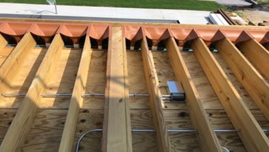
- 09: Horizontal/Lateral Bracing →
- 10: Trex® Protect™ Joist Tape →
- 11: Installing Trex® Fascia →
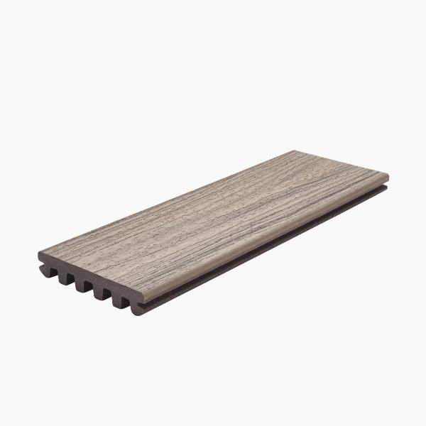
- 12: Trex Enhance® Decking Install →
- 13: Cutting in a Breaker Board →
- 14: Footings for Stair Newel Posts →
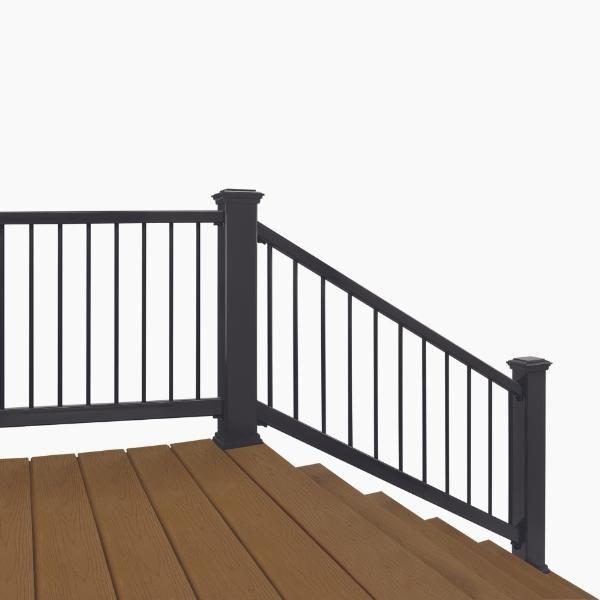
- 15: Installing Trex Enhance® Horizontal Railing →
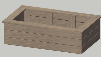
- 16: Fascia Skirt Wall →
- 17: Stairway Install →
So you're ready to get started? Watch our how-to tutorial before you start your build.
Before you begin any DIY project, make sure to wear the appropriate personal safety equipment. Eye protection, ear protection, gloves, long pants, a long-sleeved shirt, and reinforced toe shoes are recommended. Always make sure that you have a first aid kit nearby.
Step 1
Check with your local municipality for codes and permit requirements, which may be needed depending on the location, height and size of your deck. You’ll receive the necessary information at that time.
Step 2
The pool will need electricity for the circulating pump. Where is the closest outlet or source for electricity? If you bury the electrical line, you'll need to use conduit and may need to obtain an electrical permit, so check with your local municipality regarding code requirements.
Step 3
Pool safety is imperative. Keep access to the pool limited so young children cannot enter when there is no supervision.
Step 4
Insurance and the liability of having a pool on the property are important considerations. Check with your insurance company and make sure there is coverage in case of any unforeseen circumstances. If applicable, check with your homeowners association to make sure a pool is allowed in the area.
Step 5
Adhere closely to the pool manufacturer's installation guide. This can save time and keep the warranty in place.
Step 6
The pool will need to be as level as possible, so starting as close to level as possible will limit the amount of digging necessary. Make sure to stay the proper distance away from property lines, which will be designated by your local municipality as a setback to the property line.
If your property has a slope to it, assess the slope first to determine whether machinery or digging by hand will be needed. If there is a large slope on the property, excavating machinery may be required.
Try and find the most level spot. This will limit the amount of digging that will need to be done to make the base level for the pool to sit on.

Step 7
Call 811 or go to www.call811.com before any digging is done on the property, as required by law. When 811 is dialled, you will automatically be connected to a representative from your state's 811 centres, who will ask some simple questions about the location and details of the digging project. If a request is made online, the same information will be entered into a form. A representative will then come out and locate the public utilities on the property near where the proposed digging will take place. These utilities include electrical, water, natural gas, communication and sewer lines. If there are private underground utilities, such as propane or a septic system, a private company will need to be called directly to locate the underground utilities using their devices.
For a full list of considerations, check out our article on What to Consider When Planning your Above-Ground Pool Deck.
Step 1
A deck built around an above-ground pool will usually be considered a free-standing deck. This means the deck does not attach to any structure. If the deck does attach to a structure such as a house, shed or fence, let your local municipality know and they will give guidelines on the proper connection to the structure.
Step 2
A code-compliant railing will be required. The height of the railing must meet a minimum measurement guideline. The guardrail post will also have to meet structural requirements concerning the correct attachment to the frame. Railings cannot have openings exceeding 4 inches in diameter, meaning a 4 inches sphere cannot pass through any opening in the railing. Check with your local municipality for all railing codes and requirements.
Step 3
Having a self-closing gate secures the deck and access to the pool when no one is around. Check with your local municipality for specific codes related to gate safety.
Step 4
The gap between your deck boards and the coping of the pool (i.e. the capping for the edge of the pool where the pool structure will meet the surrounding deck) must be minimal. This is to minimise the possibility of injury to anyone using the pool by a toe getting stuck between the pool and the deck. Check with your local municipality for code requirements. The municipality’s gap allowance between the top of the deck board and the bottom of the coping may vary.
Step 1
Footing dimensions will vary per municipality. Check with your local municipality for guidelines on how deep, wide, and thick the footings need to be. Footing types will also vary and need to be confirmed with the local municipality before installation.
Step 2
On-site considerations for footings such as drain pipes for irrigation, water lines for irrigation, or other obstacles in the area can be addressed by moving the obstacles out of the way and around the footing.
Utilities such as electric, water, sewer, and cable should not be moved on your own and need to have a licensed contractor called to address these obstacles. It may be possible to move the post. Check the span charts and assess if moving the post and footing is an option to avoid the utility. Non-utility obstacles in the ground such as french drains and sprinkler lines can be moved to avoid the footing and post hole.
If an obstacle is not in the way but close to the footing, make sure to use caution when digging or pouring next to the obstacle.
The ideal distance of the footing to an obstacle, as well as the requirements for specific allowances on hole dimensions, is dictated by your local municipality or by the public utility company. Remember to contact www.call811 to schedule a free public utilities locator service, and to contact a private utility locator service to help locate private utilities.
Step 3
Concrete form tubes can be used around posts to contain the concrete in a certain area and not pour over pipes, conduits or other obstacles.

Step 4
Treat all posts that will be buried in the ground or in concrete with a timber preservative containing copper naphthenate for in-ground applications and coat the post to the depth that the post will be in the ground. This will prolong the life of the post.

Step 5
Plumb (i.e. test an upright surface to determine the vertical) and brace the post in both directions once it’s placed in the footing hole.

Step 6
Determine the height of the post by holding the decking material to the desired height against the edge of the pool and make a mark on the pool.
Pro Tip
The height of your post will be driven by your post-to-beam connection method, the depth of your beam, the location of your ledger, the depth of the joist, and if you have any pitch or slope to your deck.
Next, hold a piece of the joist material, which may be made of pressure-treated lumber, at that line made on the pool and mark the bottom of the joist against the pool. This mark is at the top of the post. The length of your joist material is determined by your pre-approved deck design plans.
Level across from the mark on the pool to the post and mark the height of your post. This mark is where the post will be cut. Our How-To Team demonstrates how to mark and cut the support posts in Chapter 3 of the video above.


Step 7
Next, notch the post for the beam.
To start, use a piece of the 2x timber (i.e. pressure-treated lumber) and hold it up against the post. The length of your beam material is determined by the dimensions of the deck, the spacing of the support posts, and the available lengths of the material used for the beam
Hold the beam material flush with the top of the post and mark the bottom of the beam material onto the post.

Transfer the mark to the side of the post where the beam will be installed and cut the notch. Refer to your local municipality’s building code for regulations on notching support posts.

Step 8
Treat any cut surfaces with a timber preservative to prolong the life of your deck.
Step 9
Mix the concrete according to the directions and pour it into the hole around the post. Repeat the previous steps for each of the remaining support beams. The number of support beams may vary by build.

Step 1
If your deck design includes angles, angle cuts on the beams may be necessary. If your deck design does not include angles, your beams will be cut at a 90-degree angle to the face of the beam.
Mark the desired angle on the beam material with the speed square according to your deck plans.

Set the angle of the circular saw to the angle marked on the beam material.

Pro Tip
Test the angle by cutting into the material a short distance. Adjust the angle, if needed, and cut the beam material.
Step 2
The location of the fasteners connecting the two-ply beam material together needs to be specific. Start by marking a line from the edge of the shortest point on the angle of the beam using a speed square. Transfer this line across the beam material.


Pro Tip
Use a speed square to hold a pencil at the desired marked position. Then, drag the speed square and pencil along the material to create a straight line.

In this instance, the fasteners need to be 1 inch away from the edge of the beam. Make a mark 1 inch from the line that was transferred from the shortest point of the angled beam.

Mark 1 inch from the edge of the top of the beam material and the bottom of the beam material. Transfer those marks down the entire length of the beam material.
Starting from the 1 inch mark made on the end of the beam material, measure and make a mark every 16 inches on one edge of the beam material.

The other edge of the beam material starts with a mark at 8 inches from the 1 inch mark made earlier. Repeat the process of making a mark every 16 inches. Check with your local municipality for local codes.

Fasteners will need to be placed in instances where all the marks intersect.

Step 3
Two types of fasteners can be used to connect the two pieces of beam material together. One type of fastener is a 10d ring shank hot-dipped galvanised nail.

The other type of fastener is a 3 inches structural screw. In this case, a Simpson Strong Tie SDWS 3 inches Framing screw was used. To confirm you are using approved fasteners, check with your local municipality.

Step 4
Post-to-beam connection is critical and needs to be specific with the amount of bearing the beam has on to the post.
Mark the centre point of the post by finding the midpoint of the post's width. The beam will be placed at this point so each side of the post has equal bearing for both sides of the beam.

Step 5
The post-to-beam fastener location will be in the middle of the centre point of the post and the edge of the post. In this case, the centre point of a 6x6 is 2 3/4 inches. The middle of 2 3/4 inches is 1 3/8 inches. From the edge of each side of the 6x6 post, mark 1 3/8 inches. This is the location of the fasteners from the edge of the post.

Transfer the line down the side of the post.

Fasteners need to be 2 inches down from the top of the post and 5 inches from the first fastener. In this case, the marks are made at 2 inches and 7 inches down from the top of the post.

Step 6
Fastener installation starts by drilling a wide hole in the beam material approximately 3/8 inch deep so the fastener head and washer sit flush with the edge of the post. Use a paddle bit that’s large enough to cover the washer that’s used. In this case, a 1 ¼ inches paddle bit was used.

Drill a hole through the post and beam material with a timber drill bit. Use a bit that is slightly larger than the bolt that is being installed. In this case, a ½ inch bolt was used so a 9/16 inches bit was used to drill the hole.

Use the paddle bit on the beam side to create a flat recess for the nut and washer to sit in. Keep the drill lined up with the post and not with the beam. The bolt will be coming straight out of the beam and needs to have the nut and washer straight with the post.

Slide the hot-dipped galvanised bolt with the washer through the hole.

Install the nut and washer on the other side of the beam. Using two appropriately sized wrenches tighten the bolt to be snug against the beam and post. In this case, a ¾ inch sized wrench was used as the bolts were ½ inch.

Repeat this process for the remaining support beams.

Step 1
Place the joist on top of the beam and close to the pool.
Leave a small gap between the joist and pool. The size of the gap is dependent on your pool manufacturer and your local municipality. Do not install the joist tight against the pool as the pool may shift and push against the deck, damaging the pool.
Attach the joist to the beam using a hurricane tie. In our demonstration, a Simpson Strong Tie H2.5Z was used. This is a critical connection to deter any uplift from the joist off of the beam. This connection is required by code any place a joist intersects a beam.

Step 2
Fill all the holes on the hurricane tie with the appropriate nail or screw. An 8dx 1 ½ inches hot-dipped galvanised nail is the minimum required. A structural screw can be used with the appropriate exterior coating. In this case, Simpson Strong Tie SD No.9 x 1 ½ inches Connector screws were used.

Step 3
The end rim joist is the joist that will sit on each side of the deck, creating the outer perimeter of the deck.
Use the same hurricane ties and fasteners from Step 2 to attach the end rim joist to the beam.

Step 4
The front rim joist is the joist that will be placed on the ends of the joists to create the front edge of the deck. Front rim joists can be installed with 3 inches exterior grade timber screws or 16d hot-dipped galvanised nails.
Hold the front rim joist flush with the top of the field joist and screw in the top screw.

Pro Tip
If the field joist has a small twist in it, the rim joist can be raised or lowered to align with the bottom of the field joist and the two can be screwed together. Then, the front rim joist can be moved back in place and will straighten the field joist.

Fasten the other side of the front rim joist to the field joist using the same method.
Hold the front rim joist flush with the top of the field joist and screw the top and bottom together.

Step 5
Joist layout starts by finding where the guardrail posts will be installed. Use a 2x material and lay it flat across the front rim joist.

Measure and mark where the guardrail posts will be placed. For information on guardrail post locations, refer to our Guide To Trex Transcend® Horizontal Railing Installation. Small pieces of 4x4 were used to illustrate where the guardrail posts will be placed. This can be done or simply marked on the flat 2x material.
Now that the guardrail posts are marked, the joist layout can be completed. Joists need to be laid out at a maximum of 16” on centre for Trex Enhance® Decking in a horizontal configuration (as shown in this instance). Hook the tape measure on one end of the front rim joist and look at every 16” on centre location for the joists.
If the decking was in a diagonal configuration, then the frame would have to be at a maximum of 12” on centre. Check the manufacturer's installation guide for the correct spacing. No joist in the layout should intersect with a guardrail post.
Pro Tip
If a joist does intersect with a guardrail post, move the intersecting joist to the side of the post. Leave enough room for a joist hanger if needed by measuring the size of your joist hanger. Restart the 12 inches or 16 inches on the centre layout from that point. Make sure that when the joist is moved, no spacing of the joists is more than the 12 inches or 16 inches on centre in the layout that is being done.

Mark the layout onto the front rim joist and put an ‘X’ on the side of the mark that the joist needs to go.
Step 6
Blocking needs to be placed in between every joist on top of the beam. The blocks are attached to the joist with 3 inches exterior-rated timber screws. Place the block on top of the beam tight against the joist.
Fasten the screws through the joist and into the block.
Slide the next joist up against the block and fasten with the 3 feet exterior rated timber screws.
Be sure to stagger the blocks so that they are not in a line.
Install one block on top of one side of the beam and the next block on top of the other side of the beam. This way the blocks can be accessed straight on with a screw.

Guardrail post blocking starts with the attachment of the front rim joist to the field joists on either side of the guardrail post.
Install two 8 inches Simpson Strong Tie SDWS Timber screws to go through the front rim joist and into the field joist.

Pro Tip
Fasten a piece of scrap 2x material to the underside of the joists. This will act as a helping hand to hold the guardrail post and the blocking while it is fastened in place.

Cut two pieces of the joist material to fit in between the two joists where the guardrail post is going to be placed.

Fasten these together with 3 inches exterior-grade timber screws.
Slide the two pieces of blocking in between the joists and tight against the guardrail post.
Install two 5 inches Simpson Strong Tie SDWS Timber screws through the sides of the joists and into each block. This will end up with four fasteners on each side.

Step 1
Planing the joists is a process of cutting off the high spots that milled lumber can naturally have. Joists should be installed crown up. The crown is a vertical bow in the lumber. Some crowns will be more pronounced than others, evening the crowns out will give the deck a very flat surface.
Step 2
Use a level or straight edge placed across the joists and determine where the high spots are. Mark these high points because they are where you’ll want to plane the joists to make them even.

Step 3
A power planer or a block planer can be used in this situation. The power planer will be faster, so make sure to only take a small amount of the joist at a time. The block planer will take longer and require more physicality to use.

Slowly cut away the marked high points with your selected planer. Cut a little bit at a time and check between cuts. The crown can be cut down but can’t be added back.


Step 1
Attach a small piece of 2x4 scrap material approximately 8-10 inches to the side of the post with one screw. From the bottom of the post, measure the width of the joist and fasten the block to the side of the post. In this demonstration, 7 ¼ inches was measured up from the bottom of the 2x8 joists used for the framing.

A temporary block mounted underneath the joists can also be used as a helping hand.
Step 2
Slide the post into place so that it is being held up by the temporary 2x4 block fastened to the side of the post in Step 1.
Pro Tip
The block with one screw in it will allow the post to move side to side, making it easier to plumb (i.e. test an upright surface to determine the vertical).
Using a level, plumb the post straight up and down.
Pro Tip
Clamp the level to the post to make it easy to plumb (i.e. test an upright surface to determine the vertical) the post without having to hold the level at the same time.

Step 3
Mark the front rim joist 2 inches down from the top and 2 inches up from the bottom while it’s in the centre of the post. These marks are where you’ll pre-drill your fastener holes.

Step 4
Pre-drill the holes for the fasteners with a long 7/32 inches timber drill bit. When pre-drilling, make sure to keep the drill as level as possible so the hole goes straight through the post.

Step 5
Install two 8 inches Simpson Strong Tie SDWS Timber screws through the front rim plate, guardrail post and into the two-ply guardrail post blocking.
Step 1
Horizontal and lateral bracings are installed to keep the deck from shifting or moving side-to-side when a large weight transfers on the top of the deck, like a group of people.
Step 2
On a free-standing deck, horizontal bracing will be attached under the joists, flat with two screws per joist.

These braces will be done in a chevron pattern, meaning the brace will start in the middle of the deck frame on one side and go diagonally across the deck frame to the other side on the end of the deck.
Repeat this process diagonally for the other half of the deck frame.
Step 3
Bracing from the beam to the post is also an option.
Using a 2x4, cut 45 degree angles on each side, install the brace to the beam and post with a 1/2 inch hot-dipped galvanised lag screw and washer or equivalent per figure 10 in the deck plans. Check with your local municipality for approved options. If using this bracing option, do not attach the brace to the centre post.
If using this bracing option, do not attach the brace to the centre post. A different fastener is needed for this installation step. Check with your local municipality for approved options.
Step 1
For added protection, cover all the joists from side to side using Trex® ProtectTM Joist Tape. It is designed to seal the deck fasteners as they enter the timber framing in order to minimize the potential for moisture penetration and reduce the risk of rot or decay. Trex® ProtectTM can be used on horizontal and vertical surfaces, including all joists, rim joists, beams, steps, ledger boards and under joist hangers and is available in two widths to meet your project needs.
To use, Trex® ProtectTM Joist and Beam Tape, follow this simple three-step process:
- Clean the joist surface and make sure it is dry and free of debris.
- Remove the butyl tape backing while applying the tape directly to the surface of the joist. Run your hand over the tape and firmly press it onto the joists and bearers.
- After covering all horizontal and vertical surfaces, cut the tape to your desired length with a utility knife or scissors.

Step 2
Repeat Step 1 to cover all blocking and prolong the life of the deck frame.

Step 1
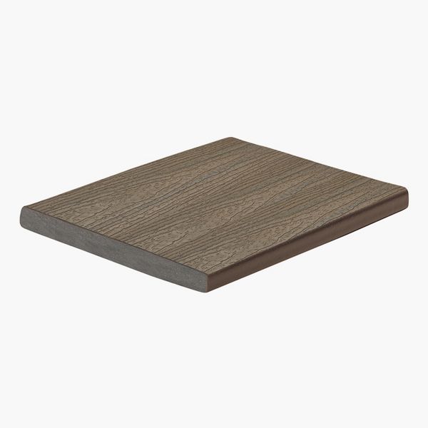
Trex® Fascia provides your deck with a complete and polished look from every angle. Trex® Fascia must be fastened every 18 inches and spacers are needed in between the fasteners.
3/16 inch spacers are attached to the rim joist every 9 inches. These spacers can be timber, plastic or composite material. In this instance, the spacers were cut out of pressure-treated lumber and all cut ends were treated with a timber protectant to prolong the life of the lumber. Spacers are used to give airflow, space for debris to fall through, and space for water to flow freely through.
Attach the spacers with 1 inch exterior grade timber screws.

Step 2
Attach the fascia to the side of the rim joist on top of the spacers.
Pro Tip
Use scrap pieces of 2x4 and place them on top of small pieces of decking. Clamp them in place. Push the fascia up against the 2x4’s and clamp in place. Now the fascia is set to the correct height of the decking which will be installed on the deck frame.

Step 3
Specific fascia screws are required for installation. Approved fasteners for Trex® Fascia are Cortex® Hidden Fastening System for Fascia, Starborn® Pro Plug® System for Fascia–Epoxy & Stainless, Starborn® Deckfast® Fascia System–Epoxy Coated* and Headcote® Stainless.
Pre-drill the holes for the fasteners with the appropriate bit supplied with the fasteners. These holes should be drilled as close to the spacers as possible. Do not install a fastener in between the spacers as it will collapse the space provided. See figure above for fastener spacing.

Step 4
Install the fastener into the pre-drilled hole using the bit provided by the fastener supplier. These specialised fasteners give the fascia the ability to expand and contract. Repeat this step for all remaining fasteners.

Step 5
If you selected fascia fasteners that include a colour-match plug, now is the time to install them on top of the fasteners. To do this, place the plug in the hole over the screw and lightly tap with a hammer.

For help determining the cost and materials for your above-ground pool deck project, check out our helpful comparison article.
Step 1
Install the first deck board with a gap of 1/8” inch between the edge of the deck board and the fascia.
Pro Tip
Use something that is 1/8 inch thick to insert between the deck board and the fascia. This will keep the gap consistent the entire length. In this case, a framing square was used, but anything can be used if it is 1/8 inch thick and can be removed. Clamp the deck board and the spacer to the fascia ensuring no movement when the fasteners are installed.

Step 2
The first deck board will need to be notched around the guardrail posts but does not need to be tight to the post.
Leave a ¼ inch gap on all sides of the guardrail post for ease of installation. The railing post sleeve and post skirt will cover these gaps so they will not be seen.

Step 3
Fasten the front edge of the deck board to the deck frame with a colour-matched composite decking screws, 2 ½ inches to 2 ¾ inches long No.8 or No.10. Fasten 1 inch in from the edge of the board and every 16 inches in the centre. In this case, the joists are placed at 16 inches on centre, and they can be followed as a pattern.
Remember an 8 inches long timber screw was placed 2 inches down from the top of the frame through the front rim plate in an earlier installation step. To avoid this fastener being hit by the face of the colour-matched fastener going through the decking, move the fastener 1 inch to the side of the 16 inches mark.

Step 4
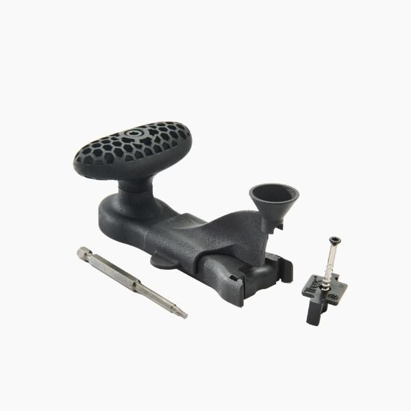
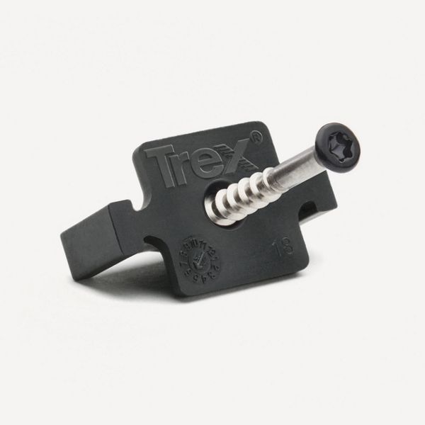
The inside of the deck boards will be fastened using Trex Hideaway® Universal Hidden Fasteners and can be installed using the Trex One Step Hidden Fastener Tool. The tool is designed to streamline the hidden fastener installation process to make it faster and more accurate. It does this by ensuring the screw is set at the proper depth on the first try and keeps the fastener straight. This fastener will fit in the groove of the deck board and space the next deck board evenly along the deck board edge. For more guidance on using Trex Hideaway® Universal Hidden Fasteners refer to our Trex® One Step Hidden Fastener Usage Guide.
Install the hidden fasteners at every joist.

Slide the next deck board into place and tap it tighten against the hidden fasteners.
Pro Tip
Use a rubber mallet to help tap the deck board into place without damaging the edges.
Repeat the process on the remaining deck boards.

Step 1
Breaker boards are used to control deck expansion by keeping the boards the same length and typically run perpendicular to the deck surface.
Using a chalk line, mark one side of the placement for the breaker board. Go from one side of the deck to the other to ensure a straight line for the breaker board to fit. For the recommended chalk see the link to Trex Install Guide under Care and Maintenance.

Pro Tip
When marking the placement of your breaker board, utilise a board in the middle of the deck to avoid “butt joints” in the field of the deck.
Step 2
Measure the width of the opening on each end of the breaker board placement. This gives a mark on each end of the deck to create a straight line and the proper opening space for the breaker board. The opening should be the width of the breaker board plus 1/8 inch on each side for a total of 5 ¾ inches in this case. To cut the deck board closest to the edge without cutting the perimeter board, a multi-tool can be used to obtain a clean cut without over-cutting into the next deck board.

Step 3
Install a temporary rip fence to guide the saw and create a straight line cut. A piece of scrap decking or scrap piece of 2x timber material can be used as long as it is straight and can be cut against.
Once your fence is installed, make sure it is as straight as possible. Fasten the material to the frame on top of the decking with screws. Do not tighten the screws all the way so the fence can easily be removed later. Set the depth of your circular saw to the thickness of your deck board. Then, holding the saw along the edge of the rip fence, cut the line.

Step 4
Install the final deck board against the pool by properly spacing it against the next deck board and the pool. Spacing should be consistent with the previously installed deck boards.
Hold the deck board in place, and use colour-matched surface fasteners or hidden deck fasteners to attach.

Step 5
Install the breaker boards by placing the first board in place by aligning it with the marks made earlier in the installation process. Give proper spacing, 1/8 inch on each side, from the edge of the deck board up to the deck ends of the perpendicular boards.
Install surface fasteners every 16 inches, 1 inch away from the edge of the board on each side. Pre-drill the screw holes 1 inch from the end of the board to avoid splitting.

Step 6
Cutting the boards at the edge of the deck will be done using the same rip fence method outlined in Step 3.
Mark the edge of where the deck board needs to be cut. Then, measure the distance from the shoe of the saw to the blade of the saw.

Step 7
Using the shoe-to-blade measurement from the saw, measure back from the mark of where the deck boards need to be cut from Step 6.
Place the rip fence at this point and loosely fasten it to the guardrail posts so it can be removed later.

Follow the rip fence with the saw, and cut the decking ends. Remove the rip fences.

Step 1
Stair newel post footings are used to secure the base of the staircase. Your local municipality will provide guidance on how deep and wide the hole for your stair newel post footings must be. Once you have this information, dig the necessary holes.

Step 2
Use concrete form tubes to pour the footer to the appropriate depth. Cut the form tube to the depth needed and place it in the hole. In this instance, the form tube was cut at 6 inches.

Mix your concrete according to the provided directions and pour it into one of the holes dug in Step 1 until it reaches the top of the form tube. Then, smooth the concrete with a scrap block of 2x material or a concrete finishing trowel.

Repeat the process, as needed.
Step 3
Clean up the tools used in a timely fashion so the concrete does not dry and make them more difficult to clean.

Step 1: Post Skirts and Sleeves
Slide post skirt over the timber guardrail post.
Pro Tip
For a simplified shopping experience, try the Trex Enhance® All-In-One Post Kit. Find a post cap, skirt, and sleeve with a new, modern design in one box.

Cut the post sleeve with a mitre saw or circular saw to the desired length. The desired post sleeve length should be sufficient to cover the pressure-treated 4x4 post.
Slide the post sleeve over the timber guardrail post and into the post skirt.

Step 2: Measuring and Cutting Top/Bottom Rails
Cut three, 12x3 ¾ inches blocks.
Lay the bottom rail against the post on the 3 ¾ inches blocks.

Be sure the baluster holes are even on each side to each post.

Once the baluster holes are even, mark the rail by transferring the post to the rail using a speed square.

Place top and bottom rails together and line up the baluster holes. Transfer lines from the bottom rail to the top rail using a speed square.

Position the top and bottom rails between posts, ensuring the baluster holes are lined up and spaced evenly. Mark rails where they intersect with the posts. Cut the top and bottom rails at this mark. A mitre saw is recommended for cleaner cuts, but a circular saw can also be used.

Step 3: Drill Hole for Foot Block
Flip the bottom rail upside down. Measure the length of the rail and mark the centre point.
Use a 3/16 inch drill bit and drill hole for the foot block at the centre point of the bottom rail. It’s important to drill the hole now, although the foot block will be installed last.

Step 4: Install Mounting Brackets
Bottom Rail
Position the mounting brackets on each end of the bottom rail so the BOTTOM of the rail will be the side WITHOUT baluster holes. Install the mounting brackets using 1 inch self-drilling screws (supplied).

Top Rail
Position the mounting brackets on each end of the top rail so the BOTTOM side of the TOP rail will be the side WITH the baluster holes. Install the mounting brackets using 1 inch self-drilling screws (supplied).
Step 5: Install Rails and Balusters
Place three, 3 ¾ inches blocks between the posts. Set the bottom rail on top of the blocks with the baluster holes facing up.

Centre bottom rail on the post and fasten through brackets into the post with 2 inches timber screws (provided).

Install the required number of balusters into the pre-drilled holes on the bottom rail.

Install the top rail starting on one end of the rail section. Insert the first baluster into the first pre-drilled hole on the bottom of the top rail baluster at a slight angle.
Slowly lower the top rail and install each baluster in the appropriate pre-drilled hole. Hold pressure on the one end of the top rail so it does not lift off the first baluster. Once all balusters are installed, apply pressure by tapping with your hand to seat the top rail in the middle and both ends, creating a snug fit.

Centre the top rail on the post and attach with three, (provided) 2 inches timber screws through the bracket into the post. Use of a 6 inches or 12 inches bit extension is recommended.

Step 6: Install Post Caps
To install a post cap, slide the cap onto the top of the sleeve and tap it into place.

(Optional): Use a clear silicone adhesive around the inside of the cap before sliding onto the post for high wind areas.
Step 7: Install Foot Block
Line up the tab on the top of the foot block with the pre-drilled hole (3/16 inch) on the bottom rail and press firmly.
Slide the foot block sleeve up and twist the turn mount to the left until the foot block is fully tightened in between the decking surface and bottom rail.
Fasten the bottom of the foot block to the decking with a 1 inch timber screw (provided).
Drop the foot block sleeve down to complete the installation.

Step 1
Cover the framing with Trex® ProtectTM Beam and Joist Tape to protect and prolong the life of the frame. The black colouring will hide the frame and the fascia will have spacing between each board and the lighter colour will be too apparent. The framing could be painted to give the same effect.

Step 2
Install the fascia over the skirt wall with approved fascia fasteners at every stud location. To confirm you are using approved fasteners, refer to our Trex® Fascia Installation Recommendations as well as the Trex Installation Guide for more information.

Step 3
Leave a minimum ¼ inch gap between the fascia boards to allow airflow under the deck. Also, leave a space at the end of each fascia deck board to allow for expansion and contraction.

Step 4
Colour-match deck plugs can be used in this application to hide the fastener heads. Once the fasteners have been installed, place a plug in the hole and lightly tap it with a hammer until the plug is flush with the top of the fascia.

Step 1
A stair stringer supports the treads and risers on either side of a staircase and needs to be cut out of 2x12 pressure-treated material. Make sure the material is approved for ground contact as the bottom of the stringer will touch the ground. To confirm you are using approved material, check with your local municipality.
Cut the stringers using both a circular saw and a jigsaw.
Use the circular saw to cut the long lines. Do not overcut past the perpendicular line with the circular saw.
Use the jigsaw to cut in the corners where the circular saw could not reach.
Refer to our How to Build Deck Stairs guide for additional instructions.


Step 2
Treat all cut ends of the stringers with a timber preservative to prolong the life of the material.

Step 3
Install the two side stringers.

Step 4
Install the header at the bottom of the two outside stringers.
Use two 3 inches exterior timber screws to attach the header to each of the stringers.

Step 5
Make sure the stairway is square. This means that the stair stringers are at an exact 90-degree angle to the deck. It also means that the bottom of the stairway has 90-degree angles on both sides of the stringers.
One way to check if your stairway is square is by measuring diagonally from corner-to-corner of the stairway. The two measurements should be equal. If they are not, move the stairway in small increments one way or the other until both diagonal measurements are equal.

Step 6
Level the stairway. Start with the front-to-back level. Place a level on the run of the stringer and brace the bottom of the stairway up by clamping it to a post or sliding a shim under the header. Raise or lower the stairway to make it level.

Place a level on the header at the bottom of the stairway. This will level the stairway from side to side. Raise or lower the other side of the stairway to make it level.

Step 7
Install the newel posts at each corner by clamping the newel post in place and plumbing the newel post to make sure it is straight up and down.

Fasten the newel posts with 5 inches Simpson Strong Tie SDWS Timber screws.

Double the header at the bottom of the stairway by putting two pieces of lumber together to act as one piece of lumber, and fasten them together with Simpson Strong Tie 3 inches SDWS Framing screws.
Step 8
Lay out the next stringers by measuring from the side and marking the appropriate spacing for the decking that is being applied. Mark an ‘X’ on the side of the line where the stringer needs to be placed.
For more information on determining spacing, refer to the Trex Installation Guide.


Step 9
Install the remaining stringers by pushing the top of the stringer against the top support block and fastening it.
Refer to our How-to Build Deck Stairs guide for additional instructions on fastening.

Align the bottom of the stringer with the layout mark and flush it to the top of the header. Pre-drill a hole for the 5 inches Simpson Strong Tie SDWS Timber screw. Fasten the screw through the header and into the stringer.

Install joist hangers to the stringers on the inside of the header. Attach with Simpson Strong Tie SD Connector screws No.9 X 1 ½ inches.
Step 10
Install the riser material on the front of the stringers below all treads. Fasten through the fascia material into the stair stringers with the appropriate fasteners.
Step 11
Install the treads on top of the stringers. These will be two pieces of the decking boards cut to the width of the stairway.
Install the treads with colour-matched composite decking screws. The screws should be 2 ½ inches to 2 ¾ inches long No.8 or No.10 composite decking screws. Leave a ¼ inch gap between the deck boards.
Step 12
Install fascia to the outside of the stringer to create a clean and finished look. See Chapter 16 for more details.


Materials
1/2" x 7" Hot-Dipped Galvanised Bolts with Washers and Nuts
3" Exterior-Grade Wood Screws
Exterior Rated Simpson Strong Tie SD Connector Screws
Gravel


More Resources to Explore
This content was partially or fully generated by AI and has been reviewed by our team to ensure accuracy and relevance.


Copyright © 2025 Trex Company, Inc. All rights reserved.
Photos and videos © 2025 Warner Bros. Discovery, Inc. or its subsidiaries and affiliates. All trademarks are the property of their respective owners. All rights reserved.
- Country
-
Australia
-
Austria
-
Bahrain
-
Brazil
-
Canada
-
Chile
-
Colombia
-
Costa Rica
-
Cyprus
-
Czech Republic
-
Fiji
-
France
-
Germany
-
India
-
Ireland
-
Israel
-
Kuwait
-
Mexico
-
Netherlands
-
New Zealand
-
Norway
-
Oman
-
Qatar
-
Saudi Arabia
-
South Africa
-
Spain
-
Sweden
-
Switzerland
-
Turkey
-
United Arab Emirates
-
United Kingdom
-
United States
-
Venezuela
By choosing your country, you acknowledge that you have read Trex's Privacy Policy
Are you in the USA or Canada?
By choosing YES or NO, you acknowledge that you have read Trex's Privacy Policy